Synthesis Technology: FM and Wavetable
There are a number of different technologies or algorithms used to create sounds
in music synthesizers. Two widely used techniques are Frequency Modulation (FM)
synthesis and Wavetable synthesis.
A D V E R T I S E M E N T
FM synthesis techniques generally use one periodic signal (the modulator) to
modulate the frequency of another signal (the carrier). If the modulating signal
is in the audible range, then the result will be a significant change in the
timbre of the carrier signal. Each FM voice requires a minimum of two signal
generators. These generators are commonly referred to as "operators", and
different FM synthesis implementations have varying degrees of control over the
operator parameters.
Sophisticated FM systems may use 4 or 6 operators per voice, and the
operators may have adjustable envelopes which allow adjustment of the attack and
decay rates of the signal. Although FM systems were implemented in the analog
domain on early synthesizer keyboards, modern FM synthesis implementations are
done digitally.
FM synthesis techniques are very useful for creating expressive new
synthesized sounds. However, if the goal of the synthesis system is to recreate
the sound of some existing instrument, this can generally be done more
accurately with digital sample-based techniques.
Digital sampling systems store high quality sound samples digitally, and then
replay these sounds on demand. Digital sample-based synthesis systems may employ
a variety of special techniques, such as sample looping, pitch shifting,
mathematical interpolation, and digital filtering, in order to reduce the amount
of memory required to store the sound samples (or to get more types of sounds
from a given amount of memory). These sample-based synthesis systems are often
called "wavetable" synthesizers (the sample memory in these systems contains a
large number of sampled sound segments, and can be thought of as a "table" of
sound waveforms which may be looked up and utilized when needed).
Wavetable Synthesis Techniques
The majority of professional synthesizers available today use some form of
sampled-sound or Wavetable synthesis. The trend for multimedia sound products is
also towards wavetable synthesis. To help prospective MIDI developers, a number
of the techniques employed in this type of synthesis are discussed in the
following paragraphs.
Looping and Envelope Generation
One of the primary techniques used in wavetable synthesizers to conserve
sample memory space is the looping of sampled sound segments. For many
instrument sounds, the sound can be modeled as consisting of two major sections:
the attack section and the sustain section. The attack section is the initial
part of the sound, where the amplitude and the spectral characteristics of the
sound may be changing very rapidly. The sustain section of the sound is that
part of the sound following the attack, where the characteristics of the sound
are changing less dynamically.
Figure 4 shows a waveform with portions which could be considered the attack
and the sustain sections indicated. In this example, the spectral
characteristics of the waveform remain constant throughout the sustain section,
while the amplitude is decreasing at a fairly constant rate. This is an
exaggerated example, in most natural instrument sounds, both the spectral
characteristics and the amplitude continue to change through the duration of the
sound. The sustain section, if one can be identified, is that section for which
the characteristics of the sound are relatively constant.
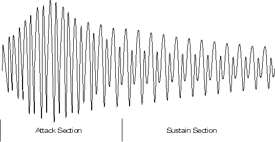
Figure 4: Attack and Sustain Portions of a Waveform
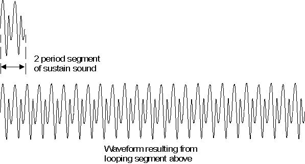
Figure 5: Looping of a Sample Segment
A great deal of memory can be saved in wavetable synthesis systems by storing
only a short segment of the sustain section of the waveform, and then looping
this segment during playback. Figure 5 shows a two period segment of the sustain
section from the waveform in Figure 4, which has been looped to create a steady
state signal. If the original sound had a fairly constant spectral content and
amplitude during the sustained section, then the sound resulting from this
looping operation should be a good approximation of the sustained section of the
original.
For many acoustic string instruments, the spectral characteristics of the
sound remain fairly constant during the sustain section, while the amplitude of
the signal decays. This can be simulated with a looped segment by multiplying
the looped samples by a decreasing gain factor during playback to get the
desired shape or envelope. The amplitude envelope of a sound is commonly modeled
as consisting of some number of linear segments. An example is the commonly used
four part piecewise-linear Attack-Decay-Sustain-Release (ADSR) envelope model.
Figure 6 depicts a typical ADSR envelope shape, and Figure 7 shows the result of
applying this envelope to the looped waveform from Figure 5.
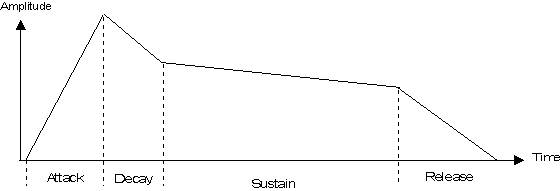
Figure 6: A Typical ADSR Amplitude Envelope

Figure 7: ADSR Envelope Applied to a Looped Sample Segment
A typical wavetable synthesis system would store sample data for the attack
section and the looped section of an instrument sound. These sample segments
might be referred to as the initial sound and the loop sound. The initial sound
is played once through, and then the loop sound is played repetitively until the
note ends. An envelope generator function is used to create an envelope which is
appropriate for the particular instrument, and this envelope is applied to the
output samples during playback.
Playback of the initial wave (with the attack portion of the envelope
applied) begins when a Note On message is received. The length of the initial
sound segment is fixed by the number of samples in the segment, and the length
of the attack and decay sections of the envelope are generally also fixed for a
given instrument sound.
The sustain section will continue to repeat the loop samples while applying
the sustain envelope slope (which decays slowly in our examples), until a Note
Off message is applied. The Note Off message triggers the beginning of the
release portion of the envelope.
Loop Length
The loop length is measured as a number of samples, and the length of the
loop should be equal to an integral number of periods of the fundamental pitch
of the sound being played (if this is not true, then an undesirable "pitch
shift" will occur during playback when the looping begins). In practice, the
length of the loop segment for an acoustic instrument sample may be many periods
with respect to the fundamental pitch of the sound. If the sound has a natural
vibrato or chorus effect, then it is generally desirable to have the loop
segment length be an integral multiple of the period of the vibrato or chorus.
One-Shot Sounds
The previous paragraphs discussed dividing a sampled sound into an attack
section and a sustain section, and then using looping techniques to minimize the
storage requirements for the sustain portion. However, some sounds, particularly
sounds of short duration or sounds whose characteristics change dynamically
throughout their duration, are not suitable for looped playback techniques.
Short drum sounds often fit this description. These sounds are stored as a
single sample segment which is played once through with no looping. This class
of sounds are referred to as "one-shot" sounds.
Sample Editing and Processing
There are a number of sample editing and processing steps involved in
preparing sampled sounds for use in a wavetable synthesis system. The
requirements for editing the original sample data to identify and extract the
initial and loop segments have already been mentioned.
Editing may also be required to make the endpoints of the loop segment
compatible. If the amplitude and the slope of the waveform at the beginning of
the loop segment do not match those at the end of the loop, then a repetitive
"glitch" will be heard during playback of the looped section. Additional
processing may be performed to "compress" the dynamic range of the sound to
improve the signal/quantizing noise ratio or to conserve sample memory. This
topic is addressed next.
When all of the sample processing has been completed, the resulting sampled
sound segments for the various instruments are tabulated to form the sample
memory for the synthesizer.
Sample Data Compression
The signal-to-quantizing noise ratio for a digitally sampled signal is
limited by sample word size (the number of bits per sample), and by the
amplitude of the digitized signal. Most acoustic instrument sounds reach their
peak amplitude very quickly, and the amplitude then slowly decays from this
peak. The ear's sensitivity dynamically adjusts to signal level. Even in systems
utilizing a relatively small sample word size, the quantizing noise level is
generally not perceptible when the signal is near maximum amplitude. However, as
the signal level decays, the ear becomes more sensitive, and the noise level
will appear to increase. Of course, using a larger word size will reduce the
quantizing noise, but there is a considerable price penalty paid if the number
of samples is large.
Compression techniques may be used to improve the signal-to-quantizing noise
ratio for some sampled sounds. These techniques reduce the dynamic range of the
sound samples stored in the sample memory. The sample data is decompressed
during playback to restore the dynamic range of the signal. This allows the use
of sample memory with a smaller word size (smaller dynamic range) than is
utilized in the rest of the system. There are a number of different compression
techniques which may be used to compress the dynamic range of a signal.
Note that there is some compression effect inherent in the looping techniques
described earlier. If the loop segment is stored at an amplitude level which
makes full use of the dynamic range available in the sample memory, and the
processor and D/A converters used for playback have a wider dynamic range than
the sample memory, then the application of a decay envelope during playback will
have a decompression effect similar to that described in the previous paragraph.
Pitch Shifting
In order to minimize sample memory requirements, wavetable synthesis systems
utilize pitch shifting, or pitch transposition techniques, to generate a number
of different notes from a single sound sample of a given instrument. For
example, if the sample memory contains a sample of a middle C note on the
acoustic piano, then this same sample data could be used to generate the C# note
or D note above middle C using pitch shifting.
Pitch shifting is accomplished by accessing the stored sample data at
different rates during playback. For example, if a pointer is used to address
the sample memory for a sound, and the pointer is incremented by one after each
access, then the samples for this sound would be accessed sequentially,
resulting in some particular pitch. If the pointer increment was two rather than
one, then only every second sample would be played, and the resulting pitch
would be shifted up by one octave (the frequency would be doubled).
In the previous example, the sample memory address pointer was incremented by
an integer number of samples. This allows only a limited set of pitch shifts. In
a more general case, the memory pointer would consist of an integer part and a
fractional part, and the increment value could be a fractional number of
samples. The memory pointer is often referred to as a "phase accumulator" and
the increment value is then the "phase increment". The integer part of the phase
accumulator is used to address the sample memory, the fractional part is used to
maintain frequency accuracy.
For example if the phase increment value was equivalent to 1/2, then the
pitch would be shifted down by one octave (the frequency would be halved). A
phase increment value of 1.05946 (the twelfth root of two) would create a pitch
shift of one musical half-step (i.e. from C to C#) compared with an increment of
1. When non-integer increment values are utilized, the frequency resolution for
playback is determined by the number of bits used to represent the fractional
part of the address pointer and the address increment parameter.
Interpolation
When the fractional part of the address pointer is non-zero, then the
"desired value" falls between available data samples. Figure 8 depicts a
simplified addressing scheme wherein the Address Pointer and the increment
parameter each have a 4-bit integer part and a 4-bit fractional part. In this
case, the increment value is equal to 1 1/2 samples. Very simple systems might
simply ignore the fractional part of the address when determining the sample
value to be sent to the D/A converter. The data values sent to the D/A converter
when using this approach are indicated in the Figure 8, case I.
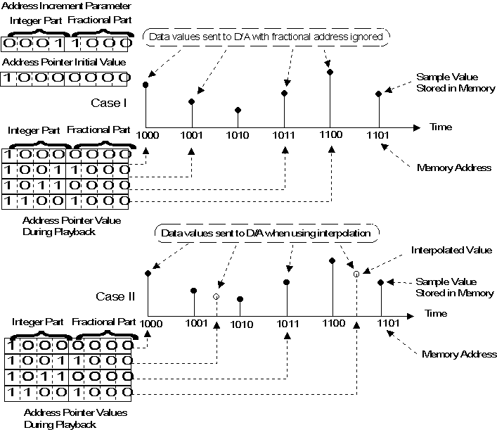
Figure 8: Sample Memory Addressing and Interpolation
A slightly better approach would be to use the nearest available sample
value. More sophisticated systems would perform some type of mathematical
interpolation between available data points in order to get a value to be used
for playback. Values which might be sent to the D/A when interpolation is
employed are shown as case II. Note that the overall frequency accuracy would be
the same for both cases indicated, but the output is severely distorted in the
case where interpolation is not used.
There are a number of different algorithms used for interpolation between
sample values. The simplest is linear interpolation. With linear interpolation,
interpolated value is simply the weighted average of the two nearest samples,
with the fractional address used as a weighting constant. For example, if the
address pointer indicated an address of (n+K), where n is the integer part of
the address and K is the fractional part, than the interpolated value can be
calculated as s(n+K) = (1-K)s(n) + (K)s(n+1), where s(n) is the sample data
value at address n. More sophisticated interpolation techniques can be utilized
to further reduce distortion, but these techniques are computationally
expensive.
Oversampling
Oversampling of the sound samples may also be used to improve distortion in
wavetable synthesis systems. For example, if 4X oversampling were utilized for a
particular instrument sound sample, then an address increment value of 4 would
be used for playback with no pitch shift. The data points chosen during playback
will be closer to the "desired values", on the average, than they would be if no
oversampling were utilized because of the increased number of data points used
to represent the waveform. Of course, oversampling has a high cost in terms of
sample memory requirements.
In many cases, the best approach may be to utilize linear interpolation
combined with varying degrees of oversampling where needed. The linear
interpolation technique provides reasonable accuracy for many sounds, without
the high penalty in terms of processing power required for more sophisticated
interpolation methods. For those sounds which need better accuracy, oversampling
is employed. With this approach, the additional memory required for oversampling
is only utilized where it is most needed. The combined effect of linear
interpolation and selective oversampling can produce excellent results.
Splits
When the pitch of a sampled sound is changed during playback, the timbre of
the sound is changed somewhat also. The effect is less noticeable for small
changes in pitch (up to a few semitones), than it is for a large pitch shift. To
retain a natural sound, a particular sample of an instrument sound will only be
useful for recreating a limited range of notes. To get coverage of the entire
instrument range, a number of different samples, each with a limited range of
notes, are used. The resulting instrument implementation is often referred to as
a "multisampled" instrument. This technique can be thought of as splitting a
musical instrument keyboard into a number of ranges of notes, with a different
sound sample used for each range. Each of these ranges is referred to as a
split, or key split.
Velocity splits refer to the use of different samples for different note
velocities. Using velocity splits, one sample might be utilized if a particular
note is played softly, where a different sample would be utilized for the same
note of the same instrument when played with a higher velocity. This technique
is not commonly used to produce basic sound samples because of the added memory
expense, but both key splitting and velocity splitting techniques can be
utilized as a performance enhancement. For instance, a key split might allow a
fretless bass sound on the lower octaves of a keyboard, while the upper octaves
play a vibraphone. Similarly, a velocity split might "layer" strings on top of
an acoustic piano sound when the keys are hit with higher velocity.
Aliasing Noise
Earlier paragraphs discussed the timbre changes which result from pitch
shifting. The resampling techniques used to shift the pitch of a stored sound
sample can also result in the introduction of aliasing noise into an instrument
sound. The generation of aliasing noise can also limit the amount of pitch
shifting which may be effectively applied to a sound sample. Sounds which are
rich in upper harmonic content will generally have more of a problem with
aliasing noise. Low-pass filtering applied after interpolation can help
eliminate the undesirable effect of aliasing noise. The use of oversampling also
helps eliminate aliasing noise.
LFOs for Vibrato and Tremolo
Vibrato and tremolo are effects which are often produced by musicians playing
acoustic instruments. Vibrato is basically a low-frequency modulation of the
pitch of a note, while tremolo is modulation of the amplitude of the sound.
These effects are simulated in synthesizers by implementing low-frequency
oscillators (LFOs) which are used to modulate the pitch or amplitude of the
synthesized sound being produced.
Natural vibrato and tremolo effects tend to increase in strength as a note is
sustained. This is accomplished in synthesizers by applying an envelope
generator to the LFO. For example, a flute sound might have a tremolo effect
which begins at some point after the note has sounded, and the tremolo effect
gradually increases to some maximum level, where it remains until the note stops
sounding.
Layering
Layering refers to a technique in which multiple sounds are utilized for each
note played. This technique can be used to generate very rich sounds, and may
also be useful for increasing the number of instrument patches which can be
created from a limited sample set. Note that layered sounds generally utilize
more than one voice of polyphony for each note played, and thus the number of
voices available is effectively reduced when these sounds are being used.
Digital Filtering
It was mentioned earlier that low-pass filtering may be used to help
eliminate noise which may be generated during the pitch shifting process. There
are also a number of ways in which digital filtering is used in the timbre
generation process to improve the resulting instrument sound. In these
applications, the digital filter implementation is polyphonic, meaning that a
separate filter is implemented for each voice being generated, and the filter
implementation should have dynamically adjustable cutoff frequency and/or Q.
For many acoustic instruments, the character of the tone which is produced
changes dramatically as a function of the amplitude level at which the
instrument is played. For example, the tone of an acoustic piano may be very
bright when the instrument is played forcefully, but much more mellow when it is
played softly. Velocity splits, which utilize different sample segments for
different note velocities, can be implemented to simulate this phenomena.
Another very powerful technique is to implement a digital low-pass filter for
each note with a cutoff frequency which varies as a function of the note
velocity. This polyphonic digital filter dynamically adjusts the output
frequency spectrum of the synthesized sound as a function of note velocity,
allowing a very effective recreation of the acoustic instrument timbre.
Another important application of digital filtering is in smoothing out the
transitions between samples in key-based splits. At the border between two
splits, there will be two adjacent notes which are based on different samples.
Normally, one of these samples will have been pitch shifted up to create the
required note, while the other will have been shifted down in pitch. As a
result, the timbre of these two adjacent notes may be significantly different,
making the split obvious. This problem may be alleviated by employing a digital
filter which uses the note number to control the filter characteristics. A table
may be constructed containing the filter characteristics for each note number of
a given instrument. The filter characteristics are chosen to compensate for the
pitch shifting associated with the key splits used for that instrument.
It is also common to control the characteristics of the digital filter using
an envelope generator or an LFO. The result is an instrument timbre which has a
spectrum which changes as a function of time. An envelope generator might be
used to control the filter cutoff frequency generate a timbre which is very
bright at the onset, but which gradually becomes more mellow as the note decays.
Sweeping the cutoff frequency of a filter with a high Q setting using an
envelope generator or LFO can help when trying to simulate the sounds of analog
synthesizers.
|